




Welding Works in Manual Mode but Not in Automatic Mode: Cycle Diagnosis
A real resistance welding case involving an industrial accumulator: comparing manual and automatic operation, examining the welding sequence and identifying a cycle timing issue.
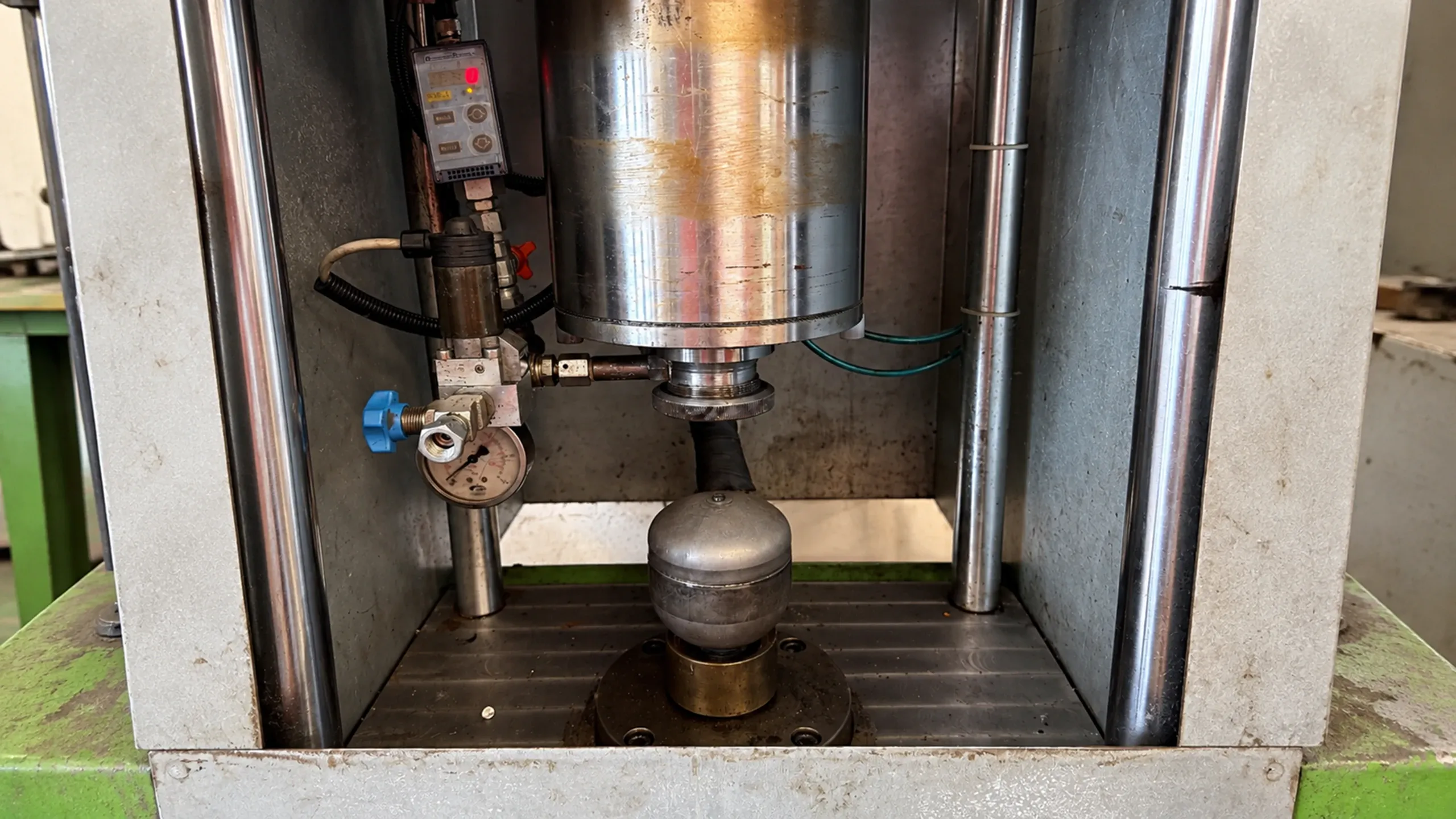
A resistance welding problem at a manufacturing company in Opera, near Milan, Italy, revealed a clear difference between manual and automatic operation.
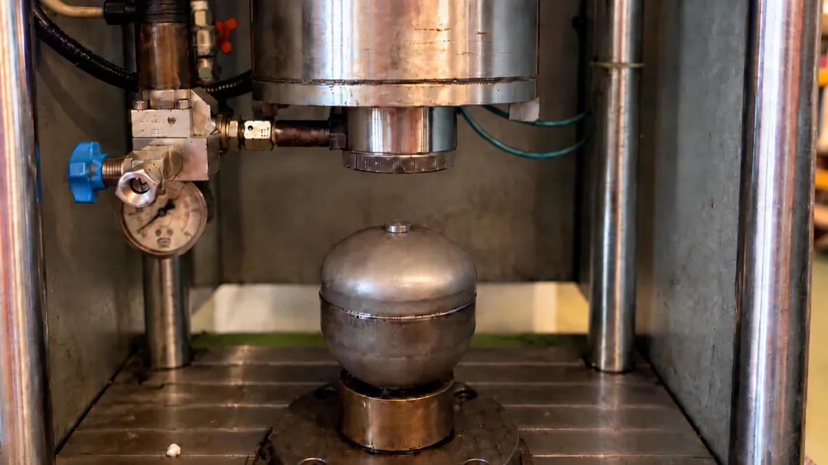
The cap of an industrial accumulator could be welded in manual mode, but the same operation failed to produce a satisfactory weld during the automatic cycle.
This difference gave the A.T.S. technician a starting point for the investigation. Rather than immediately treating the issue as a fault in the welding equipment, the technician reproduced it on several accumulators and compared how the process behaved in both operating modes.
The checks gradually narrowed the investigation to the automatic welding sequence.
Particular attention was paid to three stages: the electrode moving down towards the cap, the moment it made contact with the component and the application of welding current.
The investigation identified a timing mismatch in the PLC-controlled sequence. The programmed welding time was too short in relation to the time needed for the electrode to reach the cap and establish proper contact.
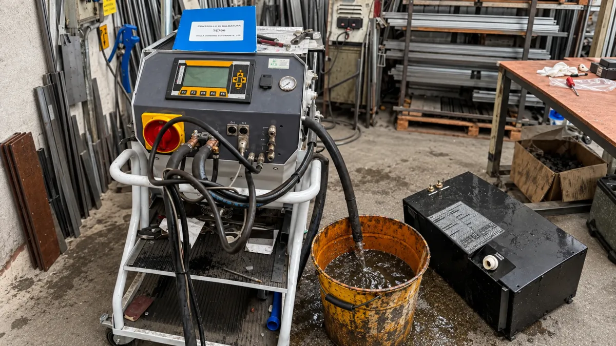
Further trials were performed using a TECNA TE550 welding controller. By adjusting the available welding parameters and observing the response of the equipment, the technician gathered additional information about the behaviour of the process.
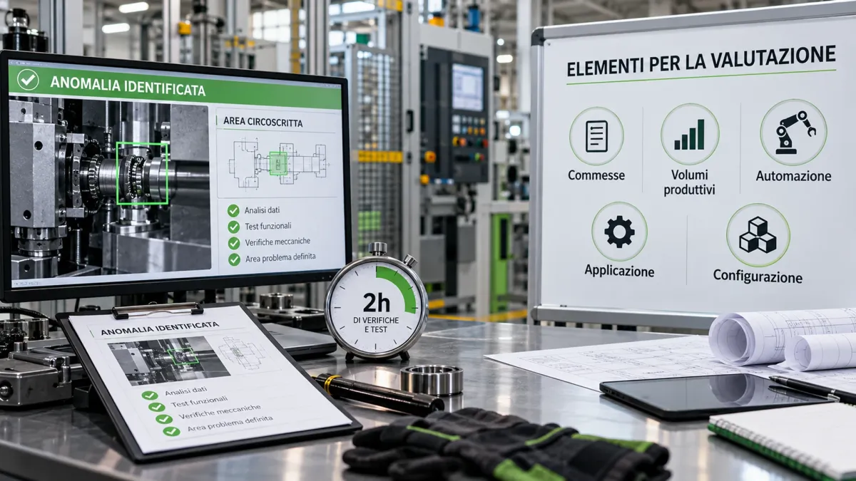
The technical assessment took approximately 2 hours. It helped identify the area of the automatic cycle responsible for the problem and provided the customer with information for the next stage of evaluation.
The case documents an application-specific investigation, not a confirmed permanent repair. Welding sequence timing and process parameters must be established according to the machine, the components and the actual operating conditions.
The case at a glance
Reproducing the Fault Before Investigating
Before examining the welding cycle settings, the A.T.S. technician needed to establish whether the fault could be reproduced consistently.
Tests were carried out on several industrial accumulators to determine whether the unsuccessful weld was an isolated occurrence or a recurring problem under the operating conditions being investigated.
The comparison between manual and automatic operation confirmed a clear difference:
- Manual mode: the cap could be welded.
- Automatic mode: the welding process failed to produce a satisfactory joint.
Since the same behaviour was observed during the checks, the investigation moved towards the timing of the automatic sequence.
The next step was to examine how the individual stages of the welding cycle were coordinated, rather than treating the problem as an occasional welding defect.
Automatic Welding Cycle Timing
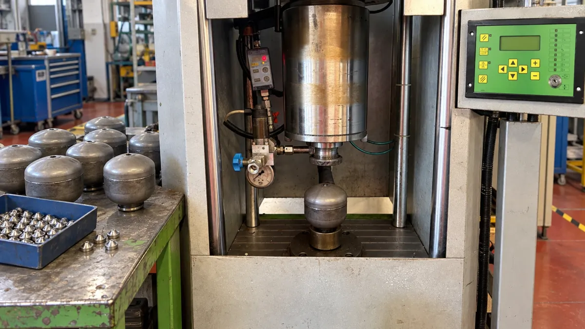
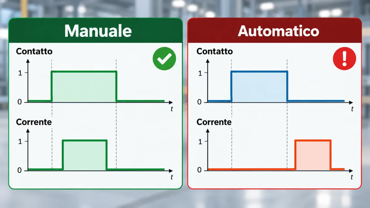
The investigation revealed a timing mismatch between the electrode movement and the application of welding current.
In automatic mode, current was being applied before the electrode had properly reached and settled against the accumulator cap.
The time allowed by the programmed sequence was too short for the electrode to complete its downward movement and establish the required contact with the component.
As a result, part of the welding current application period was effectively taking place while the electrode was still moving, rather than with the electrode correctly positioned against the cap.
This affected the conditions under which the weld was formed and explained why the automatic cycle failed to produce the same result as manual operation.
The issue was therefore linked to the coordination between electrode positioning and welding current timing, rather than simply to the ability to weld the component.
The Role of the PLC and Welding Controller
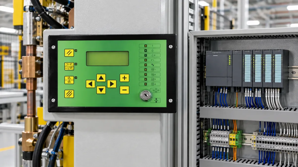
In automated resistance welding, the machine sequence and the welding parameters need to be considered separately. The PLC coordinates the machine's movements and operating sequence, while the welding controller manages the welding cycle and its associated settings.
In this case, the investigation identified a timing issue within the PLC-controlled sequence.
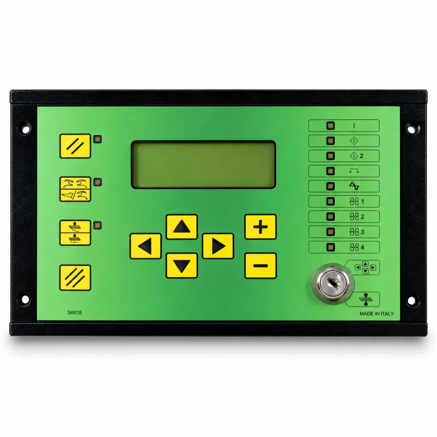
Welding trials were carried out using a TECNA TE550 microprocessor-based welding controller, designed to manage resistance welding parameters and cycle functions.
The investigation went beyond checking whether welding current was being supplied. The technician examined how the different stages of the operation were timed in relation to one another:
- Command to lower the electrode;
- Electrode movement towards the component;
- Contact and correct seating against the cap;
- Application of welding current;
- Execution of the weld.
By comparing these stages, A.T.S. was able to narrow down the part of the automatic sequence requiring further investigation.
The issue was not simply whether current was available, but whether it was being applied at the correct point in the welding cycle.
Welding Tests Carried Out Using the TECNA TE550 Controller
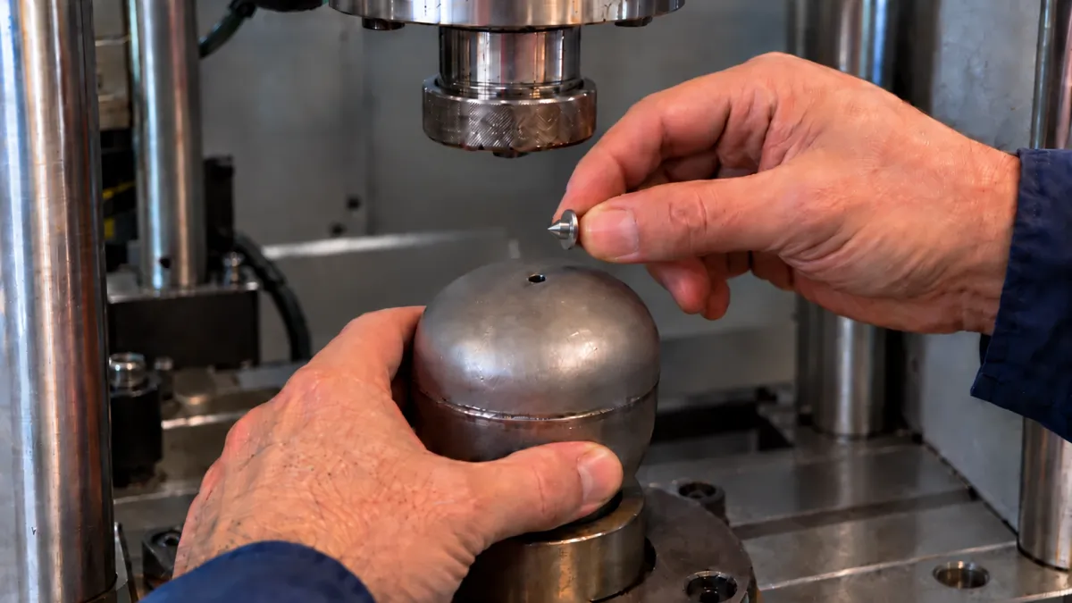
The welding trials took place at TECNA, using the industrial accumulators intended for the customer's actual production application.
Rather than testing unrelated components, the assessment focused on the behaviour of the equipment when welding the parts involved in the reported problem.
The tests covered:
- Inspection of the component to be welded;
- Welding in manual mode;
- Operation of the automatic welding cycle;
- Comparison of the results from both modes;
- Adjustments to the available welding parameters;
- Observation of the process under different test conditions.
The purpose was not to establish a standard set of welding parameters. It was to understand how this particular application responded when the operating conditions were changed.
The trials at TECNA helped identify the differences between manual and automatic operation and pinpoint the timing-related issues affecting the automatic welding sequence.
 (TE550) Tecna
Programmable control for resistance welding with 250 programs, ideal for spot welders, roller welders and industrial automation
Read more
Why Comparing Manual and Automatic Operation Was Essential
The most revealing finding was not the failed weld itself, but the fact that the same accumulator cap could be welded in manual mode and not during automatic operation.
This difference gave the A.T.S. technician a much clearer starting point. If welding was possible under manual control, the investigation needed to look beyond the component and examine how the automatic cycle was being executed.
The checks therefore focused on the relationship between:
- The programmed welding sequence;
- Cycle timing;
- Electrode movement towards the cap;
- The moment welding current was applied;
- The welding parameters used during automatic operation.
Comparing these stages helped narrow down the problem considerably.
What had initially been reported as “the cap is not being welded” could now be described more accurately:
“The automatic welding sequence does not correctly synchronize the welding current timing with the electrode contact phase.”
This distinction provided a specific technical direction for the investigation, rather than treating the unsuccessful weld as a general equipment fault.
Before and After the Diagnosis
| Before the intervention | After the intervention |
|---|---|
| Cap not welded during automatic operation | Fault narrowed down to the automatic welding sequence |
| Welding possible in manual mode | Difference between manual and automatic operation used as a diagnostic indicator |
| Root cause not yet identified | Cycle timing identified as a critical factor |
| Parameters requiring verification | Parameter adjustment tests carried out |
| Investment decision still uncertain | Additional technical information available to support the decision |
The Result: Diagnosis Before the Investment Decision
After approximately 2 hours of inspections and welding trials, the fault had been diagnosed and narrowed down to the timing of the automatic sequence.
The tests showed that the programmed cycle did not allow sufficient time for the electrode to complete its downward movement and establish proper contact with the accumulator cap before welding current was applied.
The outcome was a technical diagnosis, not a completed modification of the production equipment. The case does not document a permanent change to the machine or the immediate purchase of a replacement system.
Instead, the customer now has a clearer understanding of the process limitations and the technical information needed to consider the available options.
Any future investment will need to take account of:
- Expected production orders;
- Required production volumes;
- The level of automation needed;
- The characteristics of the welding application;
- The equipment configuration best suited to the process.
The investigation therefore provided a technical basis for the customer's next decision, without assuming that replacing the existing equipment was necessarily the right solution.
What This Case Study Demonstrates
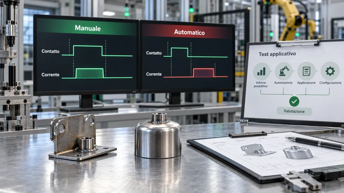
A successful manual weld does not guarantee a successful automatic cycle
When resistance welding is automated, the timing of the individual operations becomes part of the process.
A component may be perfectly weldable, yet the automatic cycle can still produce an unsatisfactory joint if electrode movement, contact with the workpiece and welding current are not correctly synchronized.
Look at the welding sequence, not just the finished joint
Inspecting a defective weld may reveal that something went wrong, but it does not always explain when or why the problem occurred.
In this case, comparing the electrode descent time with the moment welding current was applied helped identify the timing mismatch responsible for the different results in manual and automatic operation.
Test the application before committing to new equipment
Trials using the actual production component can provide valuable information when deciding whether the existing system needs adjustment or a different welding machine should be considered.
A technical trial does not have to lead directly to an equipment purchase. Its purpose is to establish what the process requires and give the customer a sounder basis for evaluating the available options.
A.T.S. Application Testing for Resistance Welding
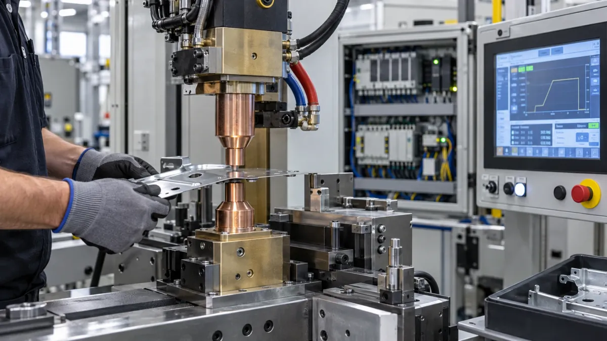
A.T.S. helps manufacturers investigate resistance welding applications, examining how the process behaves under actual operating conditions and how the welding machine, controller and automation system work together.
When production problems arise, testing the actual component can help identify the parameters or operating conditions that need further investigation. These trials also provide technical information for assessing whether the existing equipment can meet production requirements before considering an investment in a new welding system.
Need to Check Weld Quality Before Investing in a New Machine?
A weld that performs correctly in manual mode but fails during automatic operation does not necessarily mean that the welding equipment needs replacing. The difference may lie in how the automatic sequence controls the process.
Before considering a new machine, A.T.S. can help assess the application and identify which aspects of the welding cycle require further investigation.
When contacting us, please provide as much of the following information as possible:
- Component being welded;
- Material specifications and component geometry;
- Welding machine or installation currently in use;
- Installed welding controller;
- Description of the welding defect;
- Differences observed between manual and automatic operation;
- Production samples or photographs, if available.
These details provide a starting point for a technical assessment, helping us identify the most relevant checks for your specific welding application.